CUSTOMER LOGIN

Design Your CNC Process Around the Cutter, Not the Other Way Round

Design Your CNC Process Around the Cutter, Not the Other Way Round

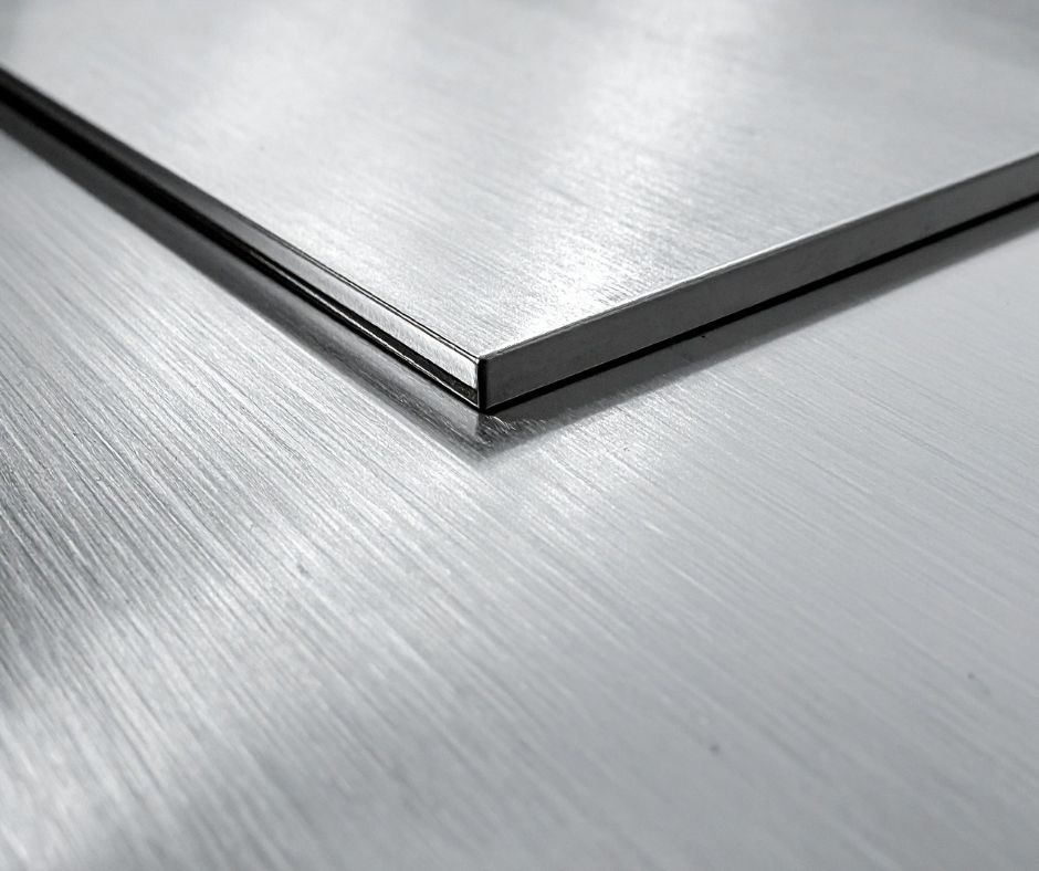
Aluminium and other non ferrous metals demand precision, heat control and reliable chip evacuation. Most experienced CNC operators know tooling choice is important, but what is sometimes overlooked is that the tool’s geometry determines the performance window.
In other words, the cutter should guide the process, not the other way round.
Modern flute designs and coatings are created to run at very specific chiploads and feed rates. When the tool is allowed to operate within that engineered range, the benefits are clear. Cleaner edges, faster cycle times, reduced heat, minimal burring and longer tool life. These gains are especially noticeable in aluminium, where heat and friction expose any mismatch between the cutter and the process.
This blog explains why aligning your CNC strategy with the cutter leads to more reliable results and how small adjustments to feeds, speeds and cutting approach can transform output in aluminium and other non ferrous materials.
Why Aluminium Needs the Right Process for the Right Tool
Aluminium behaves differently from wood, plastics and composites. It is soft, but work hardens quickly. If the cutter rubs instead of shearing, heat rises rapidly and the cutting edge deteriorates sooner than expected.
Modern aluminium tools use specific flute shapes, edge polishes and coatings designed to evacuate chips efficiently and maintain a smooth shear action. These cutters often perform best at higher feed rates than operators may be used to, particularly if their previous tools ran at slower, conservative settings.
When an older process is applied to a new cutter, results can fall short. Not because the tool is unsuitable, but because aluminium cutting is highly sensitive to chipload. A cutter designed to run fast cannot perform well if slowed to the point where chip thickness becomes too low. Underloaded cutters generate heat, cause burring, slow production and wear prematurely.
The most effective way to avoid this is to build the process around the cutter’s intended chipload and feed rate.
Case Study: A Cutter Designed for Performance
A long-standing customer recently switched to one of our aluminium cutters to improve edge quality and reduce tooling costs. They began by running it at the same speeds they had used for years with a different tool.
The results were inconsistent, and the expected performance gains were not there.
After reviewing their setup, we confirmed the cutter was being run far below its intended chipload. The tool could achieve significantly higher feed rates, and running it too slowly meant it was rubbing rather than shearing. The issue lay with the inherited process, not with the tool.
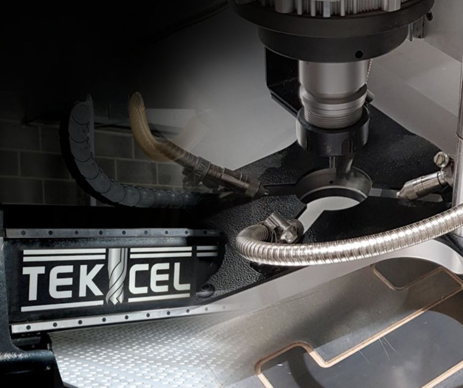
One of our engineers was onsite completing scheduled Tekcel servicing, so we asked him to assess the setup with the operator. He increased the feeds and speeds to match the cutter’s recommended range and carried out test cuts to confirm stability, accuracy and finish.
The improvement was immediate.
Cleaner edges, faster run times, no additional finishing and will result in excellent tool life.
The customer also benefitted from a lower tool purchase cost and an additional loyalty discount applied to their Tekcel service contract.
This case highlights a simple point. Performance improves when the cutter is allowed to operate as designed.
What Happens When the Cutter Dictates the Process
When the process matches the cutter’s engineered performance window, aluminium machining becomes more predictable. Correct chipload allows the tool to shear cleanly and maintain a stable temperature. As heat reduces, issues such as burring, tearing and inconsistent finish disappear.
Cycle times shorten because the tool is no longer restricted by settings unsuited to its geometry. Tool life becomes more predictable, which improves planning and reduces the likelihood of unexpected changeovers.
A cutter performs at its best only when the process supports it. Aligning feed rate, spindle speed and engagement depth with the tool’s design increases overall efficiency.

How to Build a Cutter First CNC Process for Aluminium
Understanding Chipload as the Foundation
Chipload determines whether the cutter is cutting or rubbing. Aluminium performs best when each tooth removes a consistent volume of material. Too little chipload raises heat and degrades the edge. Too much increases deflection and vibration.
The correct starting point is always calculating a chipload based on the cutter geometry, flute count and spindle speed. A single flute tool carries a larger chip per revolution, so it naturally requires a higher feed rate.
Setting Feed Rates to Support Heat Control
Heat is the main challenge in aluminium machining, and feed rate has more influence on temperature than spindle speed. A cutter designed for higher feed rates depends on momentum to clear chips. Slowing the tool traps chips against the flute and increases heat. Feed rates should be increased gradually during test cuts until the cut runs clean, bright and stable.
Matching Geometry to the Application
Flute geometry dictates how material enters and exits the cut. Single flute cutters offer excellent chip evacuation, which is why they are effective in aluminium, ACM and other non ferrous materials. Polished flutes reduce friction further. Coated cutters rely on correct chipload to make full use of their surface properties.
The tool must shape the strategy, not be restricted by a previous one.
Allowing Coatings to Perform as Engineered
Coatings reduce friction, resist heat and extend edge durability, but only when the cutter is operating within its intended load range. Running coated tools with insufficient chipload reduces the pressure required for the coating to work effectively. Correct feed and chip thickness keep coatings active and support cleaner edges and longer tool life.
Testing and Refining the Process
Test cuts provide immediate feedback. Small adjustments to feed or spindle speed reveal how aluminium reacts as chip thickness changes. The aim is to reach a point where the cutter moves efficiently, chips clear cleanly and temperature remains stable.
Aluminium communicates through sound, chip shape and edge appearance, and a short test sequence offers far more clarity than theoretical data alone.
Reviewing the Whole System
Even with the correct cutter and chipload, performance depends on the condition of the overall setup. Stable hold down, clean collets, material flatness and consistent vacuum pressure all influence accuracy and finish quality. A cutter first approach considers these factors alongside the cutting parameters.
Supporting Better Results in Aluminium Machining
Optimising aluminium tooling is part of the support we provide daily. Whether you are reviewing your current settings or exploring new options, we can help you identify the right geometry and performance window for your materials.
If you want to refine your process, assess cutter options or improve consistency in aluminium and other non-ferrous materials, our team is ready to help.
Talk to our experts for guidance on aluminium and non-ferrous CNC tooling.
Further Blog Posts
Jun / 2026
The case for an ATC router in a metal fabrication shop

Jun / 2026
What makes the Tekcel EXR CNC Router different?
May / 2026
5 signs your CNC setup is making training harder
May / 2026
Where Remakes Really Come From in CNC Supported Joinery
Apr / 2026
Why Material Handling Has Become a Bigger Issue in Modern Sign Production
Mar / 2026
Why Two Operators Get Two Different Results on the Same CNC Router

Mar / 2026
The Overlooked Link Between CNC Reliability and Staff Retention

Mar / 2026
Why Some CNC Workshops Underquote Even When Demand Is Strong